Feature
●★Wide working voltage:The trigger cycle timer delay controller module work voltage is DC 5V-36V. Meet the use of most equipment. Control Current is 30A(Max and need a heat sink! Normal temperature 15A 400W). Trigger signal source: High-level trigger (3.0V~24V)
●Different parameters can be set: OP、CL、LOP these parameters can be set. OP-on time, CL-off time, LOP-number of cycles (1—999 times, "---" means infinite cycles). These parameters are independent of each other and saved separately. All set parameters are automatically saved after power-off
●★One key emergency stop function:The module with One key emergency stop function (STOP key), with reverse connection protection, reverse connection will not burn. And it supports sleep mode. After enabling, the display will automatically turn off if without any operation within 5 minutes. Press any button to wake up
●★Unlimited switching times:This time delay switch circuit can realize the circuit high frequency fast and frequent on and off, unlimited switching times. No noise will be generated during the on-off process, no electric sparks, and no electromagnetic interference. The service life is longer than that of common electromagnetic relays
●★Dual MOS output: This MOS tube pulse generator uses dual MOS parallel active output, lower internal resistance, higher current, and strong power. 15A, 400W at normal temperature. For more details, please read the user manual
Description

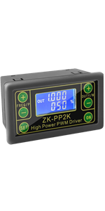
Trigger Cycle Timer Delay Controller
Trigger cycle timing
Delay switch circuit
Pulse generator
Dual MOS control
Trigger Cycle Timing Delay Switch Circuit MOS Pulse Generator DC 5V-36V Digital Tube Display

Work Mode:
P1.1:Trigger Delay Mode. Input trigger signal and then output turn ON and keep time OP. Then turn OFF after delay time OP.Keep OFF at last; The input signal is invalid if get trigger signal again during delay time OP.(Time OP can not be set 0)
P1.2:Trigger Delay Mode. Input trigger signal and then output turn ON and keep time OP. Then turn OFF after delay time OP.Keep OFF at last; Output will restart delay if get trigger signal again during delay time OP.(Time OP can not be set 0)
P1.3:Trigger Delay Mode. Input trigger signal and then output turn ON and keep time OP. Then turn OFF after delay time OP.Keep OFF at last; Output will reset and stop timing if get trigger signal again during delay time OP.(Time OP can not be set 0)
P2:Trigger Delay Mode. Input trigger signal and then output keep OFF for time OL. Then turn ON after delay time OL and then keep ON for time OP. Then turn OFF after delay time OP.Keep OFF at last.(Time OP and OL both can not be set 0)
P3.1:Trigger Delay Mode. Input trigger signal and then output turn ON and keep time OP. Then turn OFF after delay time OP and then keep OFF for time OL. Cycle the above two actions in turn.The number of cycles (LOP) can be set.Output will reset and stop timing and output OFF if get trigger signal again during loops.(Time OP and OL both can not be set 0)
P3.2:Power-ON Delay Mode. Input work power supply and then output turn ON and keep time OP. Then turn OFF after delay time OP and then keep OFF for time OL. Cycle the above two actions in turn.The number of cycles (LOP) can be set.(Time OP and OL both can not be set 0) Note:this mode no need input signal.
P4:Signal Keep Mode. Keep input signal and then output keep ON.Output turn OFF after delay time OP when the signal disappears.Reset delay time when get trigger signal again during timing.(Time OP can not be set 0)
Parameter Description:
OP: Delay time for turn On
CL: Delay time Turn OFF
LOP: Number of cycles.Range is 1-999tims.’----’ means unlimited loop

Set Parameter:
Long press:keep press button for more than 3second
1>.Enter set parameter menu by long press button SET
2>.Work mode will flash at first when set the working mode.Short press the UP/DOWN button to select working mode P1~P4.
3>.Short press SET button to enter the system parameter settings interface.
4>.In the system parameter setting interface, short press the ‘SET’ button to switch the system parameters to be modified, short/long press the UP/DOWN button to modify value.
5>.Short press button ‘STOP’ to select timing range.
6>.Short press button SET to set next parameter.
7>.Save the parameter settings and exit the settings interface when long press ‘SET’ button after all the parameters are set.
8>.Main interface:Display 000 if no output.
9>.Set interface:Long press SET button enter into set interface.Long press SET button again into main interface after set parameter.

Buyers Diagram

Package Included

Size

Installation Complete

Application
For automatic watering system DIY
Used to control curtains
For pet automatic feeding equipment
For controlling lighting
Automatic water change control for aquarium
For car headlights
For automatic curtain switch
For motor automatic control operation

|

|

|
|

|
|
|---|---|---|---|---|---|
| PEMENOL Timer Delay Relay | PEMENOL Timer Delay Cycle Module | PEMENOL Time Delay Relay Controller Board | Cycle Delay Drive Module | PWM Signal Generator Driver Module | |
| Customer Reviews |
250
|
60
|
159
|
104
|
429
|
| Price | $15.99 | $8.99 | $12.99 | $14.99 | $9.99 |
| Work Voltage | DC 5-36V | AC 85V-265V | DC 6V-30V | DC 3.3V-30V | DC 5V-30V |
| Timing Range | 0.1s-999mins | 0s-999h | 0.01s-9999mins | 0.000s~9999s | |
| Display Mode | Dual Mos Output | Dual Timing Time | Auto Sleep Function | PWM mode and PULSE mode | Speed Regulator Driver Module |